We are excited to introduce our latest sibling to you: the PW1 phono preamplifier. It is the perfect companion for a MU2, an LS1, or any other audio system of your choice. And its sound quality can be called unique by all measures. Grimm Audio’s co-founder Peter van Willenswaard was the chief designer of the ‘Phono Wizard’ PW1, and he is a rather special breed of chef cook. Since quite a few unusual things are hidden under the hood we love to give you a peak inside, guided by Peter…
One could call the PW1 an ‘understated’ device. It does not try to attract attention with a hi-fi like sound to impress its competitors. Its goal is to convey the emotion in the music and in the sound of voices and instruments. And to create a spatial image in which (if the recording allows it) you can feel the air vibrate, almost touch it. It manages to carry you along in the message of the composers and performers, of the orchestras, singer/songwriters and bands. So how did we achieve that?
Minimalism
We chose a design with as few components as possible in the signal path, under the motto: ‘what’s not in it, cannot stand in the way’. After all, the purpose of an audio circuit is to let as much music through as possible, to detract as little as possible from the sound of the recording.
In practice, this ultimately meant:
• Only 1 active component to bring the low voltage of an MC element to MM level.
• In the MM phono section 1 single active element to amplify the vulnerable input signal sufficiently to allow the RIAA correction to do its job flawlessly.
• After the RIAA again only 1 active component to convey the RIAA-corrected signal flawlessly.
• Finally 1 opamp (the most ‘musical’ one we know) to serve as a buffer between the sensitive phono circuit and the load of cables and downstream equipment, by offering a low output impedance, among other things.
Such a simple circuit is of course very attractive, so why doesn’t every manufacturer use it? Well, the straightforward circuit described above seems simple but it is absolutely not simple to design. It requires cleverly selected and extensively auditioned passive and active components. This because there is no feedback around the circuit that will correct aberrations and shortcomings. It also requires a perfectly fitting power supply for each amplifier stage and these too should be selected and fine-tuned by ear.
Of course, selecting the three active components prior to the opamp buffer is essential. FETs were chosen for a number of reasons: they have a high input impedance which is always very pleasant, their amplification behaviour is attractive (much friendlier than that of ordinary -bipolar- transistors) and they are available with various amplification factors so that no further tinkering is needed. For the MC input, a FET with extremely low noise was chosen, 0.7 nV/√Hz for the experts, which allows for a sublime signal-to-noise ratio of ≥80 dB. However, the choice of FETs is not without penalty: each copy must be measured and matched per channel. We built special measuring equipment for this. Doing extensive measurements during production is labor intense, but it is necessary for the quality of the end product.
Some will notice the relatively high harmonic distortion figure of the PW1 compared to some competitors: < 0.55% (or < -45dB). This is a result of the choice for simple FET amplification stages and because nothing is ‘corrected’ with feedback. Most designers strive for much lower distortion figures, down to 0.001% or so, but with the gain needed in phono stages there is a big risk that you design all the life out of the sound. At Grimm Audio we usually do not compromise on the distortion numbers, but with vinyl the intrinsic distortion of the record itself is so high that there is no real need for low harmonic distortion in the phono stage. Also, the distortion of FET circuitry like this is mainly of a relatively inaudible 2nd harmonic form. The positive side of our approach is that the unique way in which the passive RIAA network is implemented inherently prevents the 1st MM stage from becoming harshly overdriven. This offers an impression of endless headoom. As a result, in the actual playing of vinyl with the PW1 you will never notice any added distortion, but rather true to life dynamics.
It should not go unmentioned that the utmost care has been given to the pcb layout and the location of the various parts of the circuit. That may seem a bit exaggerated, but it certainly isn’t. We have years of experience in this area and we’ve seen countless examples of how it should not be done, with the measurable and audible consequences thereof.
Another noteworthy feature is that the design of the PW1, unlike many other phono amplifiers, does not require a separate external power supply box to prevent hum and other interference on the sensitive MC and MM inputs. To achieve this, an extremely ‘silent’ (low magnetic field) power supply transformer was developed by Guido Tent and our team with specialist manufacturer Amplimo. It is so well shielded that we could place it right on top of the MC input without any adverse effects. Nevertheless, it is placed at a generous distance of 20 cm. For the cabinet we have chosen non-magnetic materials: aluminium for the enclosure with a copper sub-chassis that provides even higher shielding to the mains input and main power supply.
Extensive setting options
In terms of settings and adjustments to different types of elements, a lot is possible with the PW1. The nominal MM sensitivity is 5 mV for 350 mV out. An additional 10 dB gain is available for the MM input if you want to use it with high-output MCs, the sensitivity is then around 2 mV. Mind that MM cartridges can deliver almost 100 mV with very deeply modulated LPs, resulting in 7 Vrms output. Both the MM input and the output electronics are able to cope with these extremes. In fact, the output of the PW1 can hardly be overdriven with its maximum level of a staggering 10 Vrms (+22 dBu)!
A separate input is provided for MC cartridges, that offers optionally 20 or 30 dB gain. If all the gain available on the PW1 is switched on, a maximum gain of 77 dB is achieved on MC, or more than 7000 x. This means that MC cartridges with ultra-low output (in the order of 0.05 mV!) can also be used. And without noise problems, because the inherent noise of the MC section is, as mentioned, extremely low.

The sliding panel on the bottom of the PW1 gives access to a wealth of load and gain settings for various cartridges. For those who find technical topics like these rather complicated, the manual includes a table in which standard settings that work well are indicated for MC, high-output MC and MM cartridges. On the other end, customers who like to lose themselves in endless experiments will find a large playground at their disposal.
In order to fine-tune the behavior of pickup elements, a series of capacitors and (for MC) termination resistors are provided on both the MM and MC inputs. For MM cartridges, capacitors of 47, 100 or 220 pF can be added to the load. Some manufacturers offer even higher values, but that seems unnecessary: with 1000 pF, for example, a peak of more than 7 dB occurs in the frequency curve at 6 kHz, which no one should want.
MC cartridges are quite insensitive to capacitive termination, but if one likes 330 pF and/or 680 pF can be added. The main load setting for MC is the resistive one. Most MC’s feel comfortable with a load resistance in the order of 5 to 10 times their own internal resistance. The PW1 has a range of options for this purpose: 33-100-330-1000 ohms and of course all combinations thereof. Disabling all extra load is also possible, the load resistance is then 47 kOhm and many MC elements feel very happy with that.
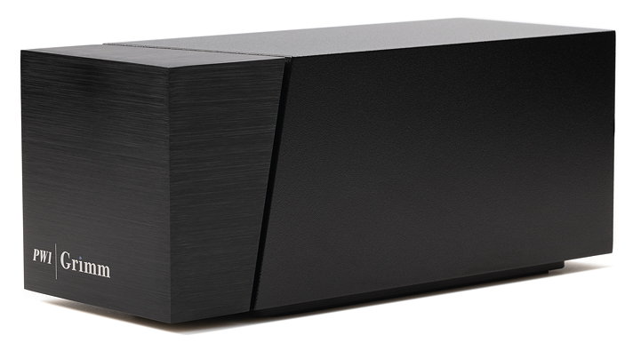
When you’re satisfied with your tweaking, close the bottom panel and put the PW1 on its feet. Now just admire its great looks (by industrial designer Michiel Uylings) and enjoy your cherished vinyl like never before.
Read the ‘Designing the PW1 phono preamplifier’ white paper >